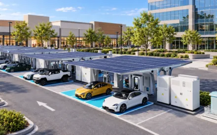

PCS, BMS and EMS are not interchangeable terms. The BMS protects and supervises the battery, the PCS converts electricity and controls AC-side power, and the EMS decides how the overall energy system should operate. A successful BESS needs all three to exchange the right data and retain safe local behaviour if communications are lost.
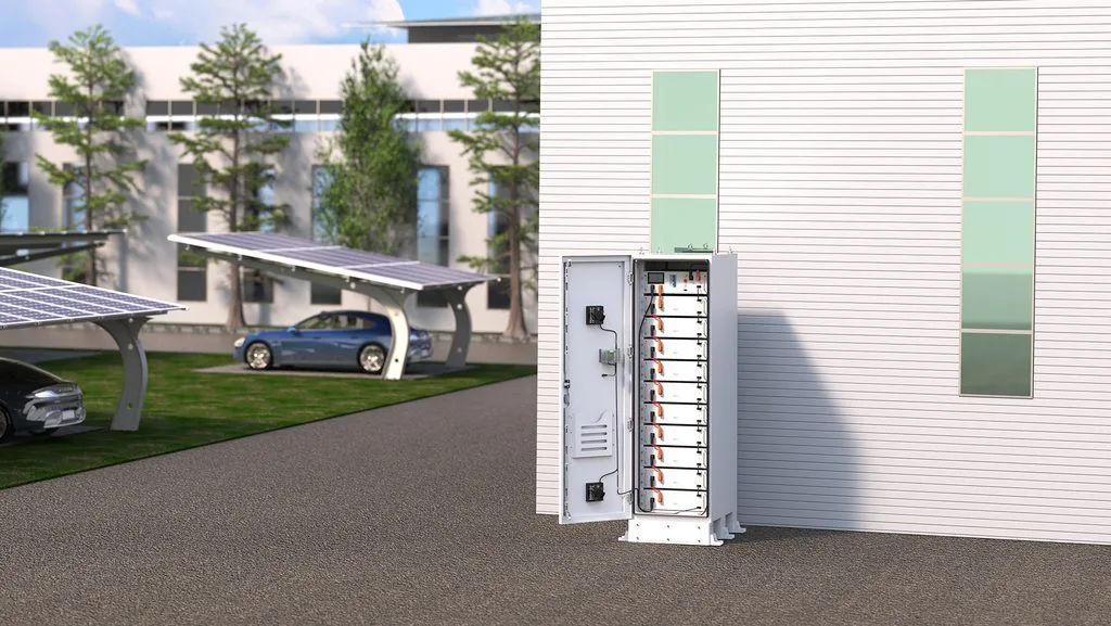
BMS: the battery’s protection and supervision layer
The battery management system monitors cells, modules, racks or containers, depending on architecture. Its responsibilities commonly include measuring voltage, current and temperature; estimating state of charge and state of health; balancing cells; applying operating limits; detecting abnormal conditions; and commanding protection actions through the battery system.
For a procurement team, the important question is not whether a product “has a BMS”—it should—but how the BMS architecture supports the required availability and serviceability. Ask how faults are isolated, what data is recorded, what limits are shared with the PCS, and what happens when a communication link fails. The BMS is a safety-critical subsystem; its function does not make the entire installation automatically compliant with local codes.
PCS: the AC/DC power interface
The power conversion system, also called a bidirectional inverter, converts battery DC power to AC power for the site and converts AC power to DC when charging. It controls active and reactive power within its ratings and participates in functions such as peak shaving, PV coupling, backup support or grid services when the selected architecture and local grid rules permit.
PCS sizing is a power decision. It must be checked against continuous load, transient demand, power factor, motor starts, grid voltage and frequency requirements, transformer capability, harmonic limits and the required islanding behaviour. A 2MWh battery connected to an undersized PCS cannot deliver the project’s required MW.
EMS: the system-level decision maker
The energy management system uses site objectives and data to schedule assets. It can decide when to charge from PV or grid, when to discharge to avoid a demand peak, how to retain backup reserve, which loads to curtail and when to coordinate a BESS with generators or EV charging.
An EMS may use forecasts and tariffs, but it also needs guardrails. Define the fallback logic if a cloud connection, meter, weather forecast or external price signal is unavailable. In a resilience application, local controls must be able to maintain an approved safe state and preserve the critical-load reserve.
The control hierarchy during normal and abnormal conditions
In normal operation, the EMS may request a charge/discharge setpoint based on tariffs and forecasts. The PCS accepts only a setpoint within its AC-side and DC-side capability. The BMS provides current allowable limits and may reduce them as temperature, state of charge or a fault condition changes. Electrical protection acts independently when it detects a fault; it is not overridden by an economic command.
During islanding or communications loss, the site should not depend on a remote dashboard to make a safe decision. Document the local controller, default PCS mode, BMS limits, load-shedding sequence and generator-start permissions. Then test loss of grid, controller, BMS/PCS communications, meter data and auxiliary power. The acceptable response may be reduced functionality rather than uninterrupted full operation, but it must be known before handover.
Communications and cyber questions buyers often miss
Specify whether the project requires Modbus, IEC 61850, DNP3 or another protocol; which party supplies meters, gateways, network switches and cybersecurity controls; and who owns user accounts and remote access. Require an agreed point list, alarm matrix, time-synchronisation method, network diagram and responsibility for firmware updates. Agree how remote support is enabled, approved, logged and revoked.
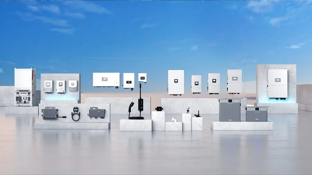
Deye Cloud supports multi-site monitoring, power-flow visibility and energy management functions. Its role should be evaluated together with the site controller, metering, communications network and local control strategy—not as a substitute for system engineering.
How the three layers work together
Imagine a facility wants to keep grid import below a demand threshold while retaining energy for an outage. The EMS sees load, tariff and state-of-charge information, then sends a requested power setpoint. The PCS delivers or absorbs AC power within its capability. The BMS provides the battery’s allowable charge/discharge limits and can restrict or stop operation if conditions require it. Protection and switchgear manage electrical faults and isolation; they are essential parts of the wider system but are not replacements for PCS, BMS or EMS.
| System | Main job | Core purchasing question |
| BMS | Battery monitoring, limits and protection | How are faults, limits, data and service isolation managed? |
| PCS | Bidirectional AC/DC conversion and power control | Can it meet continuous, transient, grid and islanding requirements? |
| EMS | Scheduling and coordination of energy assets | Does its logic protect savings and the resilience reserve? |
Example: a peak-shaving command constrained by battery protection
At 5 p.m., the EMS may request 400kW discharge to keep grid import below a demand threshold. The PCS converts that request into AC output, but it must respect thermal and electrical limits. If battery temperature rises or the BMS determines a lower discharge limit is necessary, that BMS limit takes precedence; the PCS reduces output and the EMS updates its forecast. A robust design alerts the operator and protects a configured backup reserve rather than repeatedly requesting an unavailable setpoint.
Interface questions to include in a BESS RFQ
- What protocols, meters and gateway devices are included?
- Which device owns each command during normal, islanded and fault conditions?
- What data points and alarms are available locally and remotely?
- How are time synchronisation, cybersecurity, user roles and remote updates managed?
- What are the communications-loss and controller-failure fallback modes?
- How are PCS limits reconciled with BMS limits and site protection settings?
- What testing proves the complete operating sequence before handover?
For C&I projects, a systems approach helps avoid a common integration gap: each component works in isolation, but the plant has no validated response to a real disturbance. The Deye C&I ESS solution combines energy management and storage configurations for commercial needs; Deye’s Winter Series includes grid and C&I ESS equipment, including EMS-related products.
Define acceptance tests before equipment arrives
The purchase order or commissioning plan should turn the control philosophy into observable tests: meter accuracy and direction, command tracking, BMS-to-PCS limit response, demand-threshold control, reserve enforcement, alarm delivery, generator coordination where included, and safe response to communications loss. Agree the test data, witness roles and pass/fail criteria. This makes the PCS/BMS/EMS interfaces a deliverable rather than an assumption between suppliers.
Frequently asked questions
Can an EMS replace a BMS? No. The EMS optimises the energy system; the BMS supervises and protects the battery.
Is the PCS simply an inverter? The more accurate name for PCS is Power Conversion System. It performs bidirectional conversion, but selection also needs to consider control modes, grid compliance, power quality, overload behaviour and protection integration.
Is cloud monitoring enough for a critical application? No. Remote monitoring is valuable, but the local safety and continuity response must be designed and validated independently of the cloud connection.
Specify the control architecture before selecting equipment
Share your single-line diagram, load profile, utility requirements, PV/generator/EV assets, critical-load definition and control priorities with Deye ESS. We can help you frame a solution discussion around the required PCS power, battery configuration and EMS operating logic.